1. Electronics Tools
  2. 555 Timer Calculator

555 Timer Calculator

A live 555 on your screen: watch the capacitor charge on the oscilloscope, see the LED blink, hear the tone — and get standard parts for any frequency or delay.

NE555f
Try

Live bench

+9 V0 V5551GND2TRIG3OUT4RST8VCC7DIS6THR5CTRL⏚→ +Vcc→ 10 nF330R1 1 kΩR2 68 kΩC 10 µF
R1
1 kΩ
R2
68 kΩ
C
10 µF
Vcc
9 V

Charges through R1 only — the way to get a duty cycle below 50 %.

Frequency

1.053Hz

Period
949.6 ms
High
478.3 ms
Low
471.3 ms
Duty cycle50.4 %
HIGH
LOW

Comfortable values for a standard NE555.

Step by step

  1. t_high = 0.693 × (R1 + R2) × C

    = 0.693 × (1 kΩ + 68 kΩ) × 10 µF = 478.3 ms

  2. t_low = 0.693 × R2 × C

    = 0.693 × 68 kΩ × 10 µF = 471.3 ms

  3. f = 1 / (t_high + t_low)

    = 1 ÷ 949.6 ms = 1.053 Hz

  4. D = t_high / T

    = 478.3 ms ÷ 949.6 ms = 50.4 %

0.693 is ln 2: the capacitor bounces between ⅓ and ⅔ of the supply, so the supply voltage cancels out of the timing.

Design for me

Give a frequency and duty cycle — get standard R1, R2 and C. Duty cycles of 50 % or less use the diode trick.

Hz
  • R1 180 kΩR2 390 kΩC 1.5 µF

    1.002 Hz · 59.4%

    +0.2% f · -0.6 pts D

  • R1 18 kΩR2 39 kΩC 15 µF

    1.002 Hz · 59.4%

    +0.2% f · -0.6 pts D

  • R1 1.8 kΩR2 3.9 kΩC 150 µF

    1.002 Hz · 59.4%

    +0.2% f · -0.6 pts D

Good to know

Supply doesn't change timing

The thresholds are fractions of Vcc, so 5 V or 12 V gives the same frequency. NE555 runs on 4.5–15 V.

Pick the right capacitor

Film or ceramic (C0G) keeps timing stable. Electrolytics drift ±20 % and leak — fine for blinkers, not for clocks.

CMOS 555 for batteries

TLC555 / ICM7555 draw microamps instead of milliamps, run from 2 V and go faster.

Decouple it

A 100 nF cap across the supply pins and 10 nF on pin 5 stop the output from glitching.

555 timer basics

The NE555 is a versatile timer IC. In astable mode it oscillates continuously: frequency depends on R1, R2, and C. In monostable mode it produces a single timed pulse when triggered. These formulas assume ideal components and the standard bipolar 555; actual timing may vary slightly with supply voltage and temperature.

How the 555 timer works

Astable and monostable modes

f = 1.44 / ((R1 + 2×R2) × C) t = 1.1 × R × C

Inside the NE555 two comparators watch a capacitor charge and discharge between ⅓ and ⅔ of the supply voltage. The time that takes depends only on the resistors and the capacitor, not on the supply.

Astable mode makes a continuous square wave. The capacitor charges through R1 + R2 (output high, tH = 0.693 × (R1 + R2) × C) and discharges through R2 alone (output low, tL = 0.693 × R2 × C).

Monostable mode gives one pulse each time the trigger pin goes low. The output stays high for t = 1.1 × R × C, then returns low until the next trigger.

Worked example: an LED blinker

An astable 555 with R1 = 1 kΩ, R2 = 10 kΩ and C = 100 µF drives an LED.

  1. Time hightH = 0.693 × (1k + 10k) × 100µ = 0.762 s
  2. Time lowtL = 0.693 × 10k × 100µ = 0.693 s
  3. Frequency and duty cyclef = 1 / 1.455 s ≈ 0.69 Hz, D = 11k / 21k ≈ 52 %

The LED blinks about once every 1.5 s, on slightly longer than off. Electrolytic capacitors are often ±20%, so expect the real rate to vary by that much.

Common mistakes

  • Expecting a 50 % duty cycle

    In the standard circuit the output is high for R1 + R2 and low for R2 only, so it is always above 50 %. Add a diode across R2 or make R1 much smaller than R2 to get close.

  • Making R1 too small

    R1 limits the discharge pin's current. Keep it at 1 kΩ or more on a 9–12 V supply.

  • Leaving the control pin floating

    Pin 5 picks up noise that shifts the timing. Decouple it to ground with a 10 nF capacitor.

  • Trusting a large electrolytic for precise timing

    Tolerance and leakage make long delays inaccurate. For precise timing use film capacitors with larger resistors, or a microcontroller.

555 timer FAQ

In astable mode f = 1.44 / ((R1 + 2×R2) × C), which is 1 / (tH + tL). The duty cycle is (R1 + R2) / (R1 + 2×R2).

t = 1.1 × R × C. For example, 100 kΩ and 10 µF give a pulse of 1.1 s.

Barely. The thresholds are fractions of the supply, so timing stays nearly constant from 5 V to 15 V. The CMOS versions (LMC555, TLC555) work from about 2 V.

Put a diode across R2 so the capacitor charges through R1 only, then make R1 = R2. The high and low times are then nearly equal.

The bipolar NE555 is reliable up to roughly 100 kHz; CMOS versions go higher. At the low end, delays of minutes are possible, but capacitor leakage makes them imprecise.

1 ground, 2 trigger, 3 output, 4 reset (tie to Vcc if unused), 5 control voltage, 6 threshold, 7 discharge, 8 Vcc.


Free shipping

On orders over $50

Easy returns

30-day hassle-free returns

Secure checkout

Encrypted payments

24/7 support

We're here to help

Dzduino Online Store

Eempowering engineers, students, makers, researchers, and businesses with high-quality and innovative technical solutions.

  • Sales: store@dzduino.com
  • Store: +213 550 88 88 27
  • Sales: +213 550 88 88 29
  • Support: +213 550 88 88 37
  • 043 Cite Remila (Route du Port), Tigditt - Mostaganem

Shop

  • All Categories

Support

  • Track order
  • Orders
  • Account
  • Shipping & returns
  • Shipping calculator

Company

  • About
  • Contact us
  • Site map
  • Privacy
  • Terms

Stay in the loop

New stock, maker deals, and electronics tips — straight to your inbox.

© 2026 Dzduino Electronics, All Rights Reserved

PrivacyTermsShipping & returnsShipping calculatorSite map
CIBBARIDI MobFawriPayCash
Free express shipping on orders over $50
SpecialSaleBlogPrint & CutLabContact us

Related products

Boards, modules, and kits that pair with this tool.

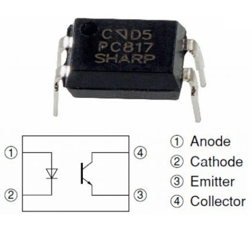
PC817C DIP-4 transistor output optocoupler

PC817C DIP-4 transistor output optocoupler

DZD 40.00Out of StockOut of Stock
LM386 Audio Power Amplifier IC

LM386 Audio Power Amplifier IC

DZD 60.00In StockIn Stock
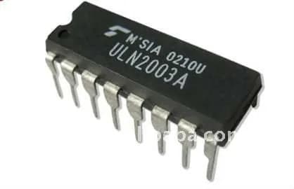
ULN2003A, Darlington Transistor

ULN2003A, Darlington Transistor

DZD 80.00In StockIn Stock
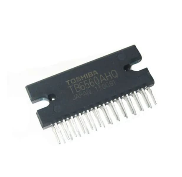
TB6560AHQ IC TB6560 Step motor Driver Toshiba

TB6560AHQ IC TB6560 Step motor Driver Toshiba

DZD 1,750.00Out of StockOut of Stock
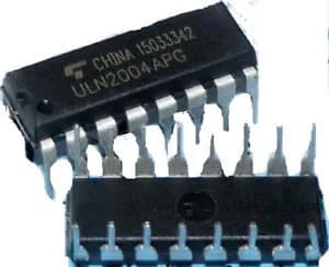
ULN2004 7NPN DIP-16 Darlington transistor array

ULN2004 7NPN DIP-16 Darlington transistor array

DZD 70.00Out of StockOut of Stock
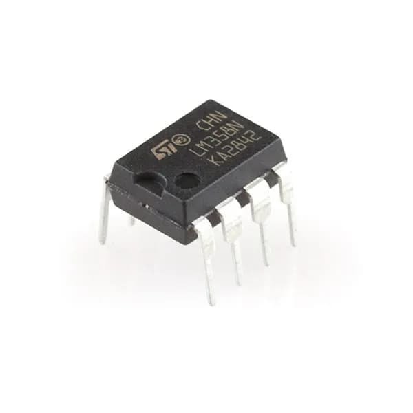
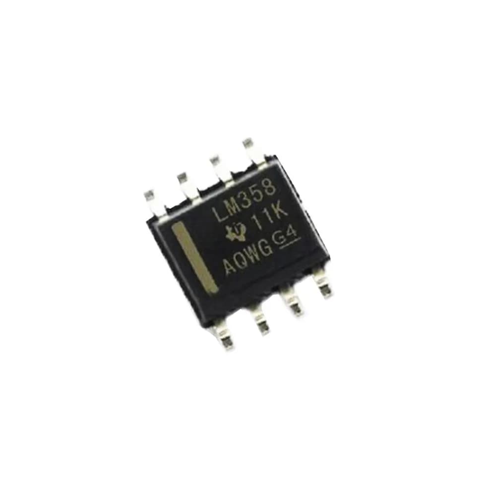
LM358 Operational Amplifier SMD SOP8

LM358 Operational Amplifier SMD SOP8

DZD 100.00In StockIn Stock
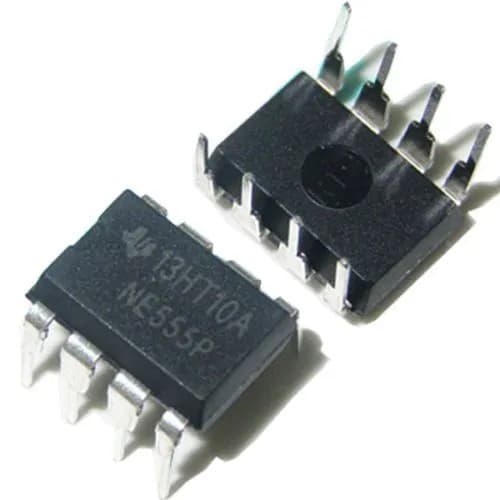
NE555P  DIP8 Single precision timer

NE555P DIP8 Single precision timer

DZD 80.00Out of StockOut of Stock
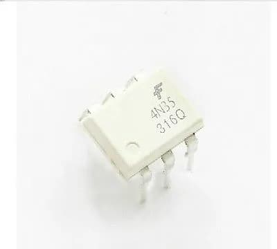
4N35 DIP-6 PHOTOTRANSISTOR OPTOCOUPLER

4N35 DIP-6 PHOTOTRANSISTOR OPTOCOUPLER

DZD 80.00In StockIn Stock
View all